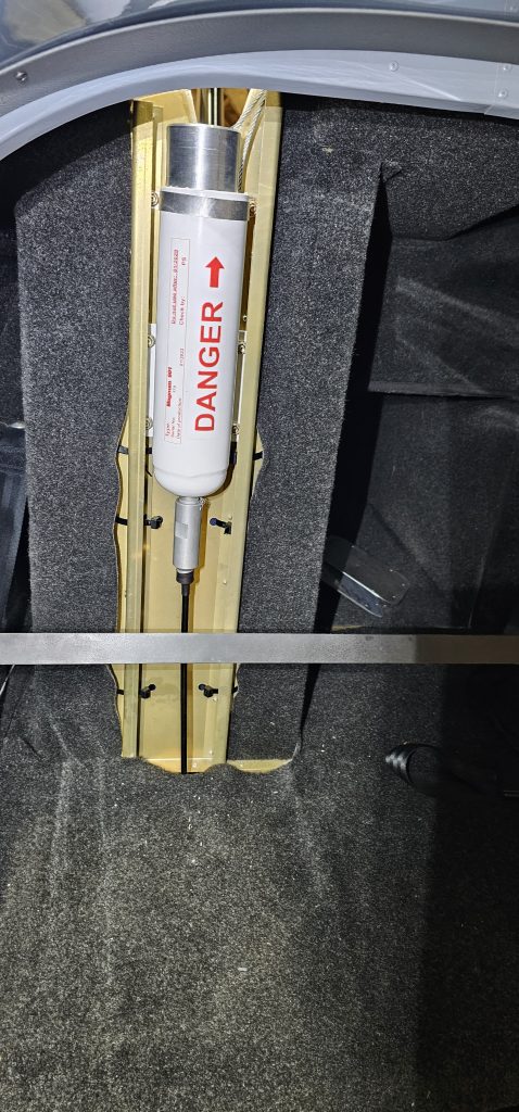
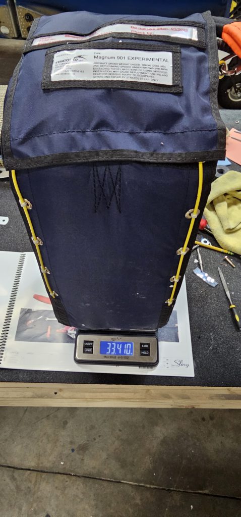
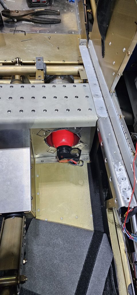
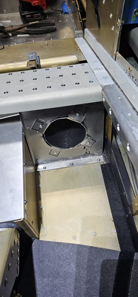
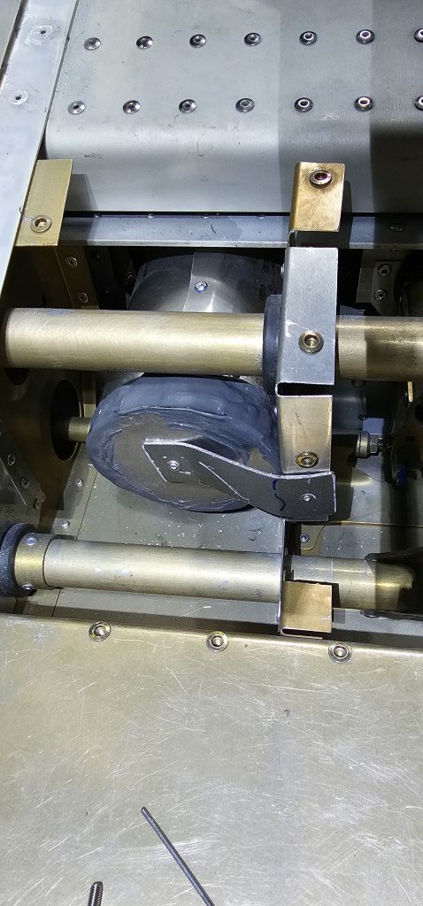
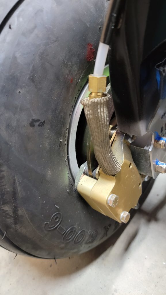
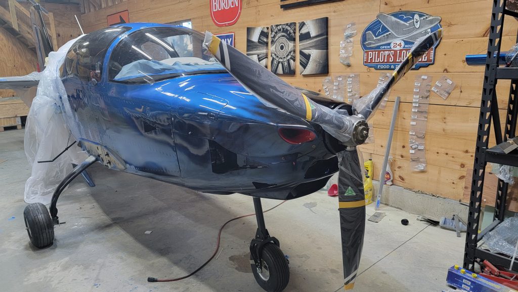
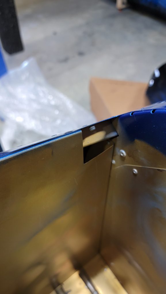
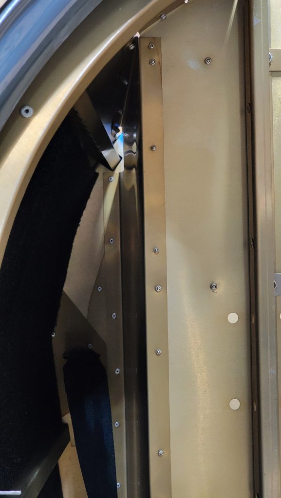
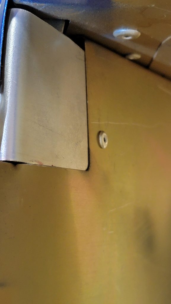
Page 2 of 10

Brake bleed ing

After 2 days of trying to make this work I gave up and posted online, please help.

I’ve bled the brakes of many cars before, I can’t say I’ve never had a problem but I do usually accomplish my goal. But I gave up doing this seemingly much smaller of a project and asked for help online.

The difficulty was that the this brake line wasn’t a line, it’s not straight, it’s actually a Tee. So how do I get both parts of the T to be air free (rhymes) at the same time. Very disappointed in myself that this solution didn’t occur to me.

The answer I received from Errol on Sling builders was,

To bleed the wheels first, by flipping the parking brake to on. Then elevate the front of the throttle quadrant, release the parking lock and bleed rest forward towards the reservoir.

Thanks Errol !!!

Brake lines and interior

I was worried about my brake lines overheating. So I purchased this thermal wire protectant tube… It’s the same thing as exhaust wrap. But it comes already in a tube, kind of like a straw. I slid that over the bottom of my brake lines. Where they touch the caliper. The thought process here is it’ll keep the end of the brake lines from heating up and traveling up to the plastic brake line.

On my interior on the bottom under the dash against the console… Those panels screw on and off with button head screws. Because I have to take them on and off periodically to do maintenance, I didn’t want to have to try to find holes in carpeting. So I cut the carpeting into strips so where the screws are, carpeting is not. I think it still looks good because it’s under the dash and it’s dark down there so you can’t see it and it will make ongoing maintenance a whole lot easier.

ELT and Radiators and Prop mock up

Oil and coolant radiator. Done. That’s all that needs to be said about that. It was literally the easiest thing I’ve done on the plane so far. Wrap the hoses with heat protectant wrap, attach done.

I hid the ELT antenna between the canopy in the rear fuselage, as pictured.

Yesterday I marked up the propeller to ensure that it fit. I had to do a lot of measurements based upon Mt propellers PDF. I cut my cowling on speculation according to those PDF measurements months ago. A long time before I actually got the prop. And thank goodness it came out good. 11 mm clearance.

That’s it for today.

Parachute and hoses

This would have been done a couple months ago but I’m still waiting on my parachute. So I find myself dragging my feet to finish up my last couple tasks. I suppose it’s a mixed blessing. It allows me to be a perfectionist and proceed very slowly.

I recently ran the radiator and oil hoses. I reran them a couple times to get it perfect. I kept changing the exact path to keep them away from the exhaust as much as possible and to eliminate sharp turns. I also used a different heat resistant wrap than comes with the plane. I used more of an automotive exhaust wrap. It is virtually the same. It is still a glass insulation weaved wrap. But it’s about twice as thick. The temperature resistance is much higher on the wrap I used. Not satisfied with simple published specifications. I did perform a heat test on the provided wrap and the new one I bought. I exposed to them both to a torch and and compared with an IR thermometer. And the automotive exhaust wrap did a lot better.

Parachute hole

I found a hole from the interior of the plane into the parachute storage area. And the parachute storage area is not sealed tightly most likely because the top has to blow off. Anyway that little hole in the back of the compartment concerned me that the warm air from the interior of the plane would leak into it and out. So I plugged it. I made sure it is smooth on the inside so the parachute would not catch on it. Not in the pictures below but I ended up adding some filler over top of it and seeing it down to make it super smooth.

Firewall wiring penetration

I didn’t feel like the factory solution was sufficient to prevent fire or carbon monoxide from penetrating through the firewall. So I created my own more airtight solution. All the wires going through the main hole, I did the following too…

I took all the wires and wrapped them in an extra wide zip tie. Standard zip ties are too small and I feel like it might pinch the wires. Then in the center where the zip tie would tighten up, I put red rtv in between the wires, so when I tighten the zip tie the RTV would squish out of the center of the wires. This whole zip tie contraption I positioned right in the hole of the firewall. Then I covered the rest of the zip tie in the red heat resistant rtv. It’s already pretty tight and almost filled up the entire hole. But I added a little extra rtv to seal the whole hole up completely. I then took more of the firewall, fire resistant, insulation and wrapped it around the wire attaching it to the firewall.

Sorry no pictures of this. My hands were too covered in RTV to use the camera.

Constant speed propeller with no manual controls, like a cirrus

One hates to give away their secrets but, I am going with a Mt propeller and rs flight system controller. That’s not the secret. The secret is how much better their support and lead times are over airmaster. I ordered my propeller and flight control system and within 3 months I received them both. Being one of the first slings to have the system on, I asked many questions and rs flight systems were extremely responsive they responded quickly and thoroughly answered my questions.

The next question is how easy is it to install…. Very easy! I’ve never installed an airmaster but comparing the instructions I believe this is way easier to install. The mt propeller is hydraulically controlled. It uses engine oil for the hydraulic pressure. So all you have to do is connect a governor with four bolts and plug in three wires that go to the brain/SCU and you are good to go. Versus Air Master where you have to install the slip ring on the propeller flange and the brushes to transfer the electricity. They seem like they’ve been problematic in wearing out at inconvenient times.

The wiring for the SCU does mean you’ll have to TAP into the two wires coming from the engine. You’ll have to tap into the HICa and the HICb. I tapped into those immediately behind the connector that way it was easy to make sure I have the correct wire. You need to tap into the can bus low and the can bus high for Lane a and b. So in total that makes four taps. The HIC connectors do have the low and high right next to each other. So I was able to find a single tap that will do two adjacent wires in one. Which makes it a really neat installation. Lane a connector will require power which is simply a positive and a negative and if you already had the airmaster power routed you can simply plug it into the SCU instead.

The wire for the governor only comes with a connector on one end. Seems like they could put the connector on the other end but they don’t. It doesn’t matter it’s a simple 15 pin serial connector and there are only four wires in the cable. So it is easy to do.

Mounting the governor to the back of the gearbox is tight but it does fit without any modifications. First you’ll have to remove the plate that sling attached to the back of the gearbox. Shown in picture. Getting the lower lower bolt is a bit of a pain but in one of my pictures I try to illustrate the approximate path I took with many connected sockets to get to it. In the picture my extension of my sockets are above the air box. But in reality my sockets were below the airbox. The picture is simply for illustrating the approximate path. The bolt supplied to the governor do not go all the way through the flange. Flange is approximately half an inch thick so I felt like that was okay. But I verified with the manufacturer and they said that was the way it was designed.

The SCU mounts inside of the plane. With the rest of the avionics sorry I did not get a picture of that but it’s pretty straightforward.

Post paint, polishing

I didn’t want anyone to think I haven’t been doing anything….

I painted the plane at my shop. It wasn’t a sterile paint booth. I did have three to five fans running with air filters to reduce the contaminants in the air. But still dust managed to get into my clear coat. So now I’ve spent the last two weeks sanding and polishing to make it smooth. It ended up using 3M compound and polish ing chemicals along with the DeWalt polisher and a Bosch hand sander. And it has been working really well but sadly it’s a lot of work. The one picture below, has dust on the right hand side and the left hand side has been polished. My process has been to wet sand with 1200 grit, then wet sand again with 1500 grit, then wet sand again with 2500 grit. Then polish with rubbing compound. Then polish with Polish.

End of this month I am supposed to get my propeller and my parachute. I should be able to look at those installed during the month of December. Then January I can move to the hangar and get it inspected. Hopefully. That might be a bit optimistic but I’ll try.

Paint

For the last week or two I’ve been doing a lot of body work and prepping for painting. Just refilling some rivet holes and make sure all of the fairings are fitting correctly. Did little to no body filler but there was a place here or there that I wasn’t happy with that required some touch up. I did not have my windshield in when I was painted nor did I have any gaskets on. When I’ve painted cars in the past, removing the gaskets was standard procedure so I thought leaving the windshield off would be essentially the same thing. I also still do not have my parachute so the parachute cover was painted before installed. I think that’s a good idea that way there’s actually paint underneath the cover and should help corrosion resistance and may even help the cover to detach easier.

I provided concept drawing of what I wanted to plan to look like to my painter. His reply was, “did you have your kids draw this with crayons.”. My response was, “no I drew it. Am I really that bad of an artist”. I took the sling dimensions from the poh and printed it out on a full size sheet of paper and colored it in. We then take off the entire plane and got the painting. We painted it in my shop and it took 3 days and made one hell of a mess. I had four fans with air filters attached going and it still wasn’t enough. So we’d have to take breaks painting occasionally to let the air clear out.

But it’s done now and I think the end result is well worth the effort.

I feel like I need to be further back to take to take a decent picture. So I will save most of the finished product pictures until later.

Tail tie-down bumper stop

A couple times now I have heard that I need to be concerned with the Sling TSI s tail slamming against the ground. What can cause this is two people getting up on the steps at the same time. My Cirrus had a rubber bumper on the rear tie down. I looked at getting that exact bumper but it feels to hard to actually cushion the blow. I tried many different materials until I found the right hardness. This material is just right. It will act like a sponge and dampen some of the impact force from the above scenario. I plan to attach it with some low quality glue. It already fits on pretty tight and I want to be able to remove it if necessary.

If a tail strike happened during take off, this material would most likely not be hard enough to provide sufficient protection but it would help. Any material that would be hard enough to protect during take off would not likely protect from a stationery tip back. It if wears out over time, It is easy and cheap to replace, so no biggie if it comes to that.

« Older posts Newer posts »