I feel like I’ve said this too many times already,, but this simple task turned out to be harder than I thought it would be.
Getting all of the hinges on the elevator to line up the same time and all of the washers in the correct locations, was quite the challenge. So I took my lessons learned from that elevator and applied them to the rudder. I glued the washers for the rudder in place also. Don’t worry, as soon as the hinges were bolted down the washers spun loose immediately. For the elevator I found it easier to start at the middle and work my way out. For the rudderI found it easier to do the top bolt first then the bottom bolt then the middle bolt. The middle bolt caused me a lot of frustration but eventually it gave up and went in.
i thought this would be an easy productive day. You’d think I would have learned by now… Nope
i started trying to attached the elevator. The day before I attached the horizontal stab, that was actually easy. When I picked up the elevator I realized that one side of it didn’t have the rivets filled. So I filled the rivets in the morning and lucky they dried quickly. I sanded them and went back to installing. I quickly realized that I would not believe able to install the washers for each oly as required. So instead of trying to wedge the washers in there with needle nose pliers, I glued them into the HS ahead of time. Don’t worry it’s crappy glue, it barely holds. As shown in the picture I put a bolt through and temporarily wedged a bolt/spacefiller in there to hold the washers tight as they dried. They held just long enough for me to slide the elevator in. Then I attached two bolts. But,, then I realized that I should adjust the length of the pushrod first. The secret to that is pushing the elevator all the way forward at some times and all the way back at other times so that you can get the bolt and wrenches in there… So I did that…skip ahead 2 hours… Then I started to reinstall the elevator. Had to reglue some washers because they broke loose. Then I started to reinstall the elevator again. All the bolts aligned miraculously very straight and went in easy. Even the elevator tips aligned with the HS. Definitely use a laser level to make sure that HS and elevator are straight. I think that is what helped. Anyway,,, another day into the past.
Another day has gone into the past. I blew today by doing three tasks.
First, I flushed my fuel lines with FUEL. I know, I know , what a crazy concept. I previously tested them, to make sure there were no leaks, with water. But now that I was ready to complete the fuel lines, I didn’t want to connect the fuel lines to the engine with water still in the fuel lines. So I grabbed a high pressure self priming pump and pumped fuel through all of my fuel lines including the return lines. It was good because I got to test again that there are no leaks.
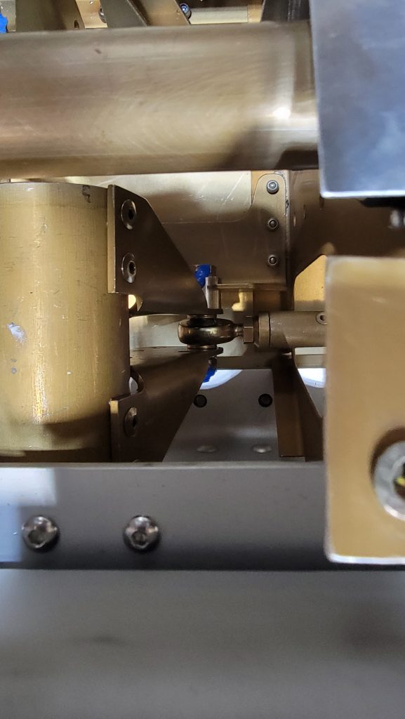
Second, I attached the aileron interconnect for the controls. This proved to be very challenging it’s very hard to get your fingers in there to put the bolt, washers and nut in place. I ended up putting the bolt through the opposite direction from what the instructions say but I think it’ll work fine. Functionally, there’s no difference. The bushing is still on the side required to act as a stop. Putting that stupid pushrod in took a very long time.
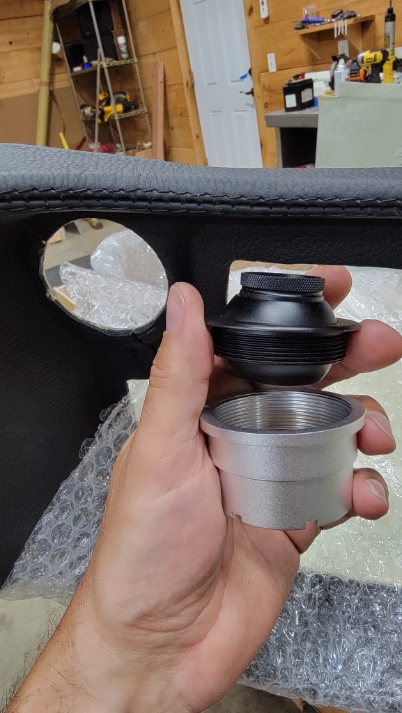
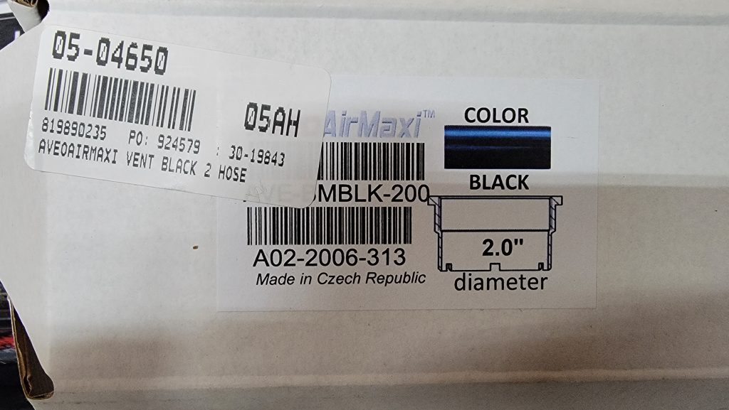
Thirdly, I replaced the air vents that come with the dash with the Aveo vents. Literally the easiest thing I have done to build this plane. It took me less than 5 minutes to do both of them.
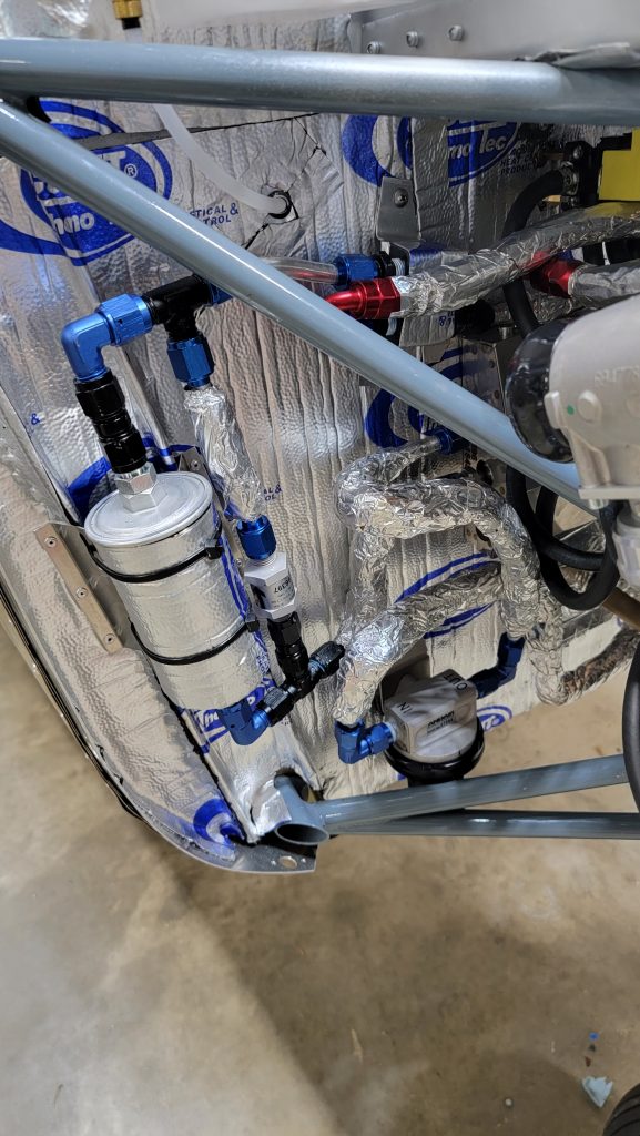
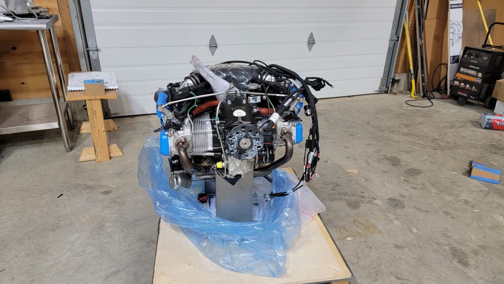
So I completed the alternator yesterday… Today I completed the fuel lines. My previous post I did the interior aluminum fuel lines,. And in another post I did the aluminum fuel lines on the outside of the firewall…. But I completed today was the Teflon fuel lines that run to the engine. I figured since the engine would be vibrating it’s probably better to have fuel lines that move also so this is the only part of the system that is not aluminum. I will also be using Teflon fuel lines to connect the wings to the fuselage. I know some other builders are using a block of aluminum for a manifold but I did not need to use that. I just used a tee instead. I did however use the Lockheed part from Patrick shines blog for the jet fuel restrictor between the input and the return lines.
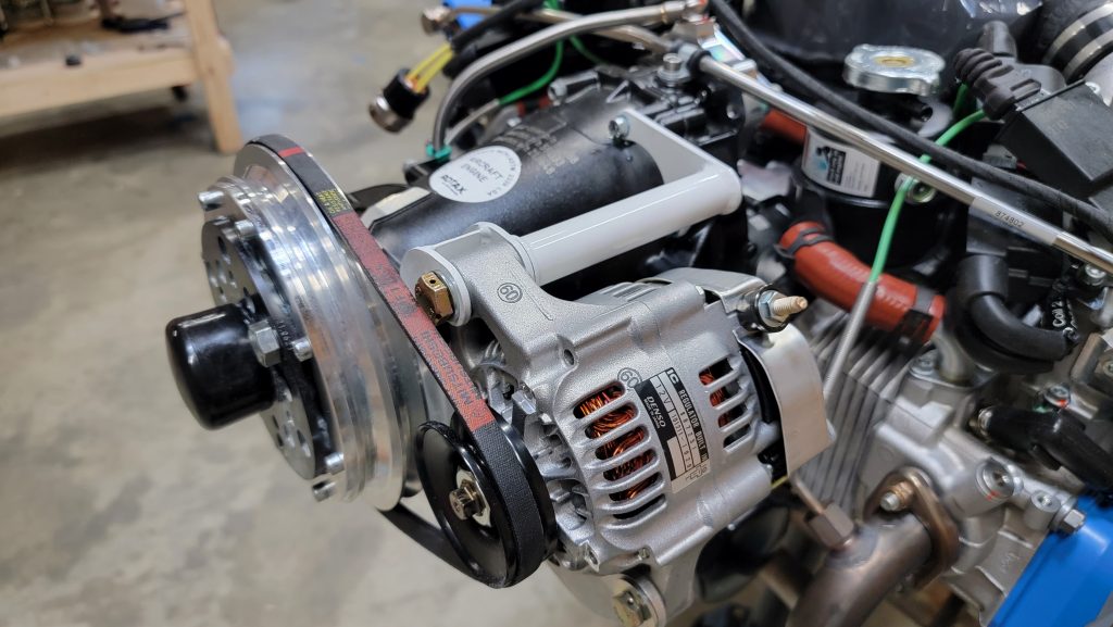
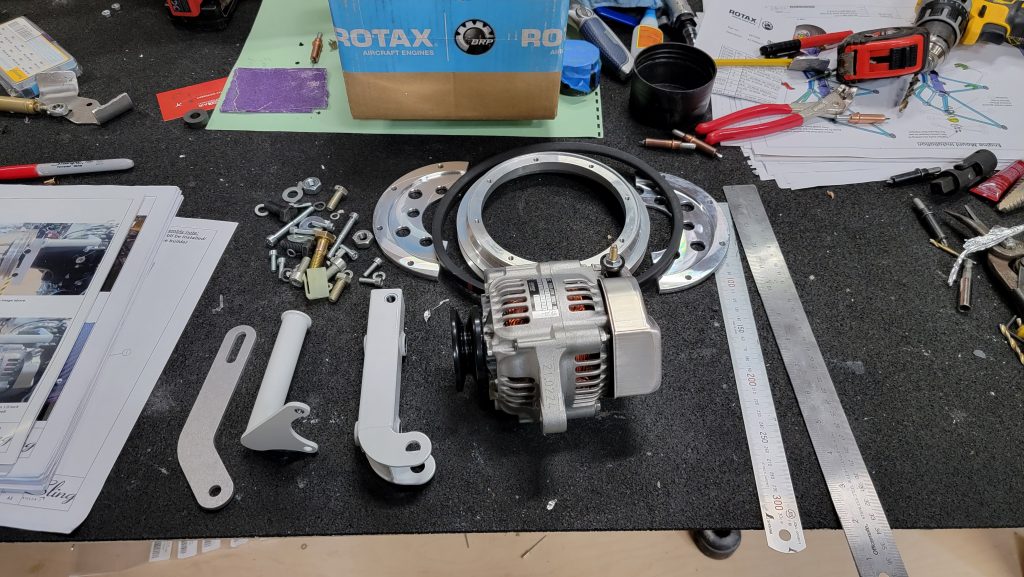
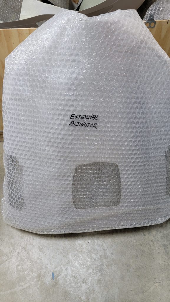
I chose to go with the external alternator for my Sling TSI. Both for the CG advantage and for having a tertiary backup alternator…. And for being able to run pitot heat and landing lights without worrying about running the battery dead.
I couldn’t find many pictures of the installation online so here are pictures of mine. The installation of the external alternator is very straightforward. You will want to connect it with a separate switch so you don’t necessarily have to always run it.
Update: my alternator is bumping the cowling. I do have the cowling with the bump out but it still bumps. It was rubbing the cowling. Can’t have that. To fix the problem I got a 25.5 inch vbelt. Shorter than the default one. It allows the alternator to sit in closer. That said it is still crazy close.
I also did research into how much horsepower the external alternator would be stealing because our little engines only make 135 to 141 horsepower every single horsepower counts. After doing the math of (UPDATED🙂 my 1hp equals 768watt per 20amps, and not all alternators are created equal, we use denso… So basically we are losing 4hp with the ext alt. …. I came to the realization that we’re losing four horsepower. Of course I took into account that the alternator is not perfectly efficient and there will be some drag loss from the belt but even then you’re talking one to one and a half horsepower which I think is worth having the extra backup. Update, four horsepower, maybe it isn’t worth it….
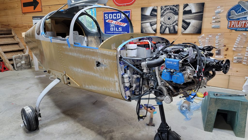
That’s right the engine has been mounted. I was sure this would be a quick and easy task. But as my life so often goes, I was completely and totally utterly wrong. Mounting the engine took me two solid days. Even now as I say it, I can’t understand why it took that long. I’m not sure. Just trying to get the engine lifted and then get all four bolts aligned and torqued and I used loctite, proved to be quite the challenge.
This deserves a separate paragraph. Having the weight of the engine on the front of the plane really brought to light that the nose wheel is too hard to turn. So I lifted the front of the plane up took the nose wheel off. I sanded down the bearings and I sand down very slightly the nose wheel itself then put it back on…. No difference…. So I took it off again sanded everything a little bit more. Then put everything back together and now it’s a lot better. And that was another day gone .
Now I sit here looking at how much the front wheel turns. It makes me a little nervous about how sharp the whole plane will actually turn. My current plane is a cirrus, it has a caster nose wheel. It will point directly 90° to either side and it will spin the whole plane on a dime. In the past, it has proved itself to be very useful.
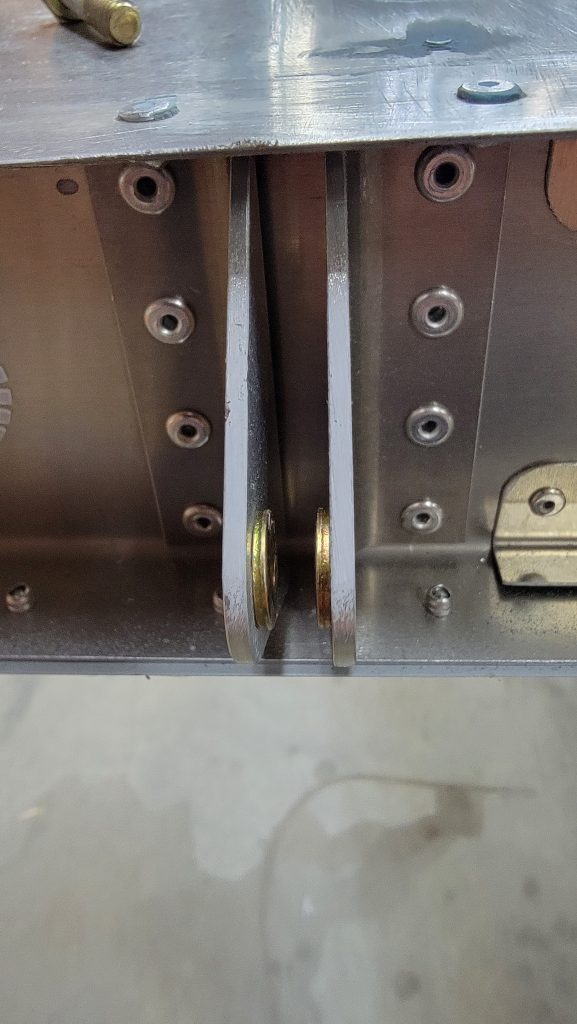
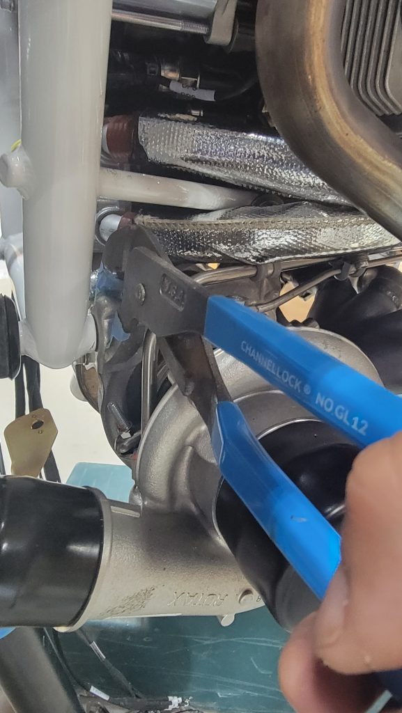
As Patrick Shine mentioned in his blog the bottom right bolt is a pain. But I also found the bottom left bolt to be a pain. For the bottom right bolt I eventually figured out that using a pair of channel locks I could squeeze the bolt from the outside of the exhaust mount and squeeze it hard enough using a clamp on the.l channel lock handle that it would hold the nut still. Pictured.
For the bottom left bolt I did as Patrick did a used a open end crescent wrench. It was still to wide to fit in the opening so I had to grind some metal off the outside of the wrench and the. It worked fine. All torqued up and ready to go.
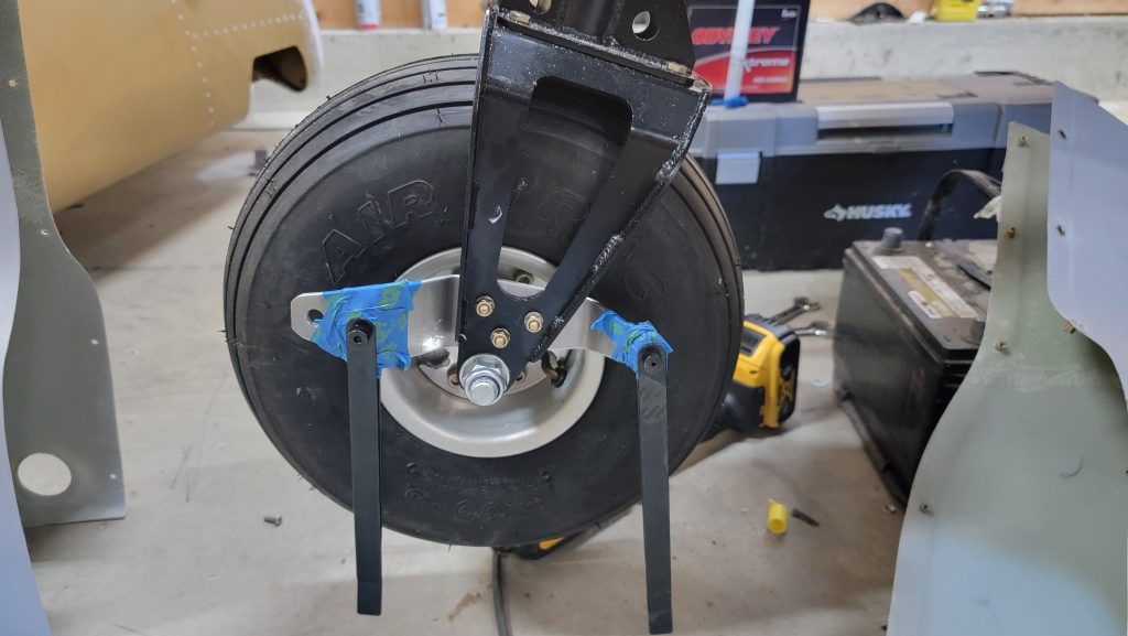
I drilled up the holes and the rivnuts for my main landing gear spats. This was easy and fairly straightforward. The nose wheel however was a challenge. I found getting the holes where the rivnuts and the tow bar connects difficult to get aligned correctly. So I used the hole finders. However, I was not able to actually find the holes with the hole finders. So before putting the fairings on, I taped the whole finders in place and then slid the fairings through the hole finders.
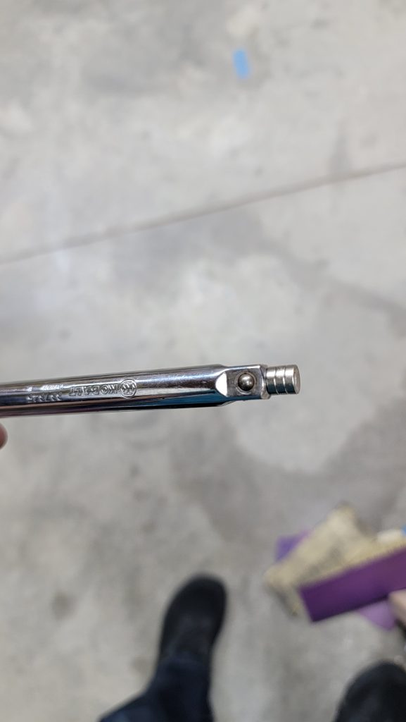
So it was only a couple months ago that I completed my ailerons. I have since moved on and have been working on other things. Then the service bulletin about the rod ends came out. I was concerned I would have to tear apart my newly constructed ailerons. As it turns out, you do not have to tear them apart but it could be challenging. There is an access hole on the side of the aileron where you can look in and see the bolt that you need to remove. But being able to remove that bolt and push it back in precisely could be a challenge. So I added some magnets onto the end of a socket extension rod. That proved to be just strong enough to hold the bolt to push it in. But more importantly it proved to be strong enough that if I repeatedly attach the magnet and pulled it back, attach the magnet pulled it back over and over and over again it would pull the bolt out, which is the trickiest part. Findung a way to pull the bolt out is a challenge otherwise. I know they have magnetic sockets but they weren’t strong enough to pull the bolt out. So as you can see in the picture I attached a bunch of my own magnets and that seemed to work.
I can’t officially recommend a replacement rod end. But you can look online and find the one that comes with the aircraft and you can find replacement rod ends that are three times stronger. The cost about 40 bucks a piece but I think the additional strength will be worth it.
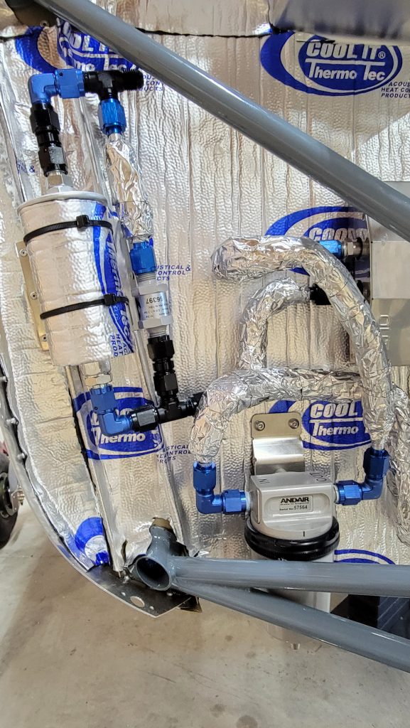
Inside the cabin I’m using aluminum fuel lines. I’m also using limited aluminum fuel lines on the outside of the firewall. After the fuel filter is where I will switch to use teflon fuel lines that run to the engine.
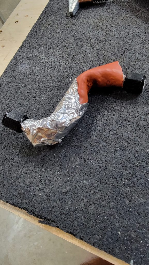
I’m also wrapping the fuel lines insulation in heat resistant aluminum tape. The picture below shows an aluminum line half wrapped in insulation and half wrapped in foil tape, for the purpose of illustration only. I’m kind of paranoid about vapor lock so I’m trying to do everything I can to resist heat in the fuel lines. I also went out of the way to keep the lines as low as possible as long as possible.
I know this is far from standard, so please feel free to comment and tell me all the ways I’m doing it wrong.
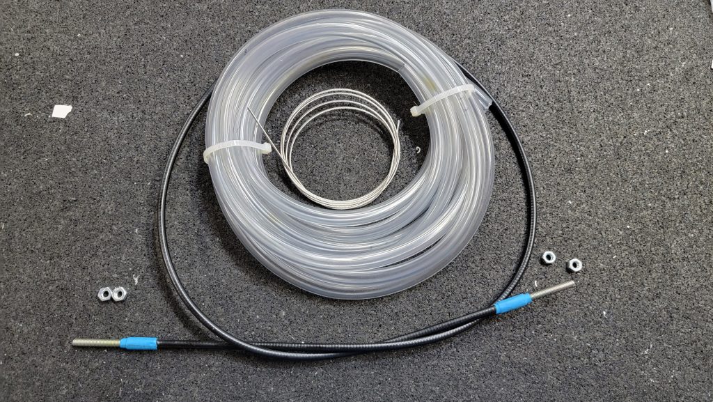
Yesterday I made my throttle cable and ran it through the firewall. Nothing particularly interesting to report here. Very straightforward. Just one item of note, the instructions never actually say to run the wire through the sheathing. I guess that would seem obvious. But if the wire and sheathing are in separate bags not near each other it might confuse someone. So I am mentioning it.
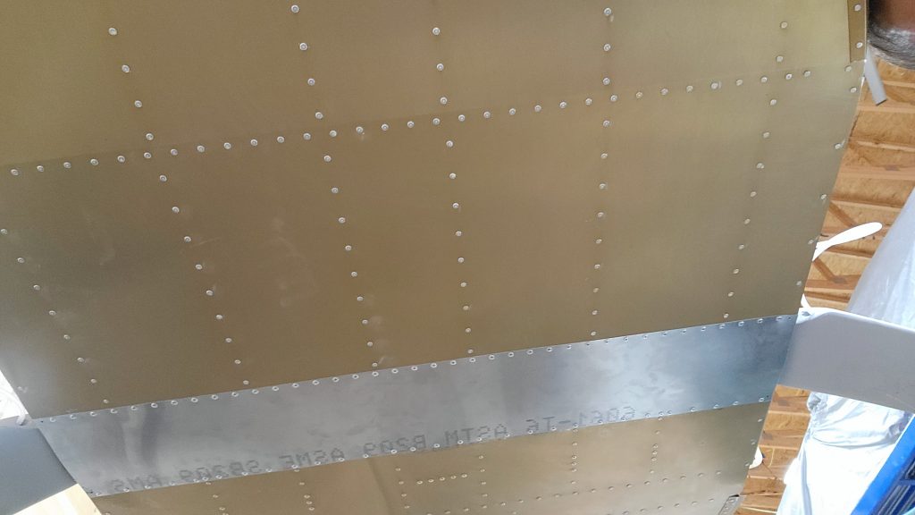
I installed the under carriage skin. I was worried that the leading edge of the skin is the lowest point on the plane bottom so it might catch some wind and before I attached the skin I could see light up through the bottom. I was worried about air getting in there. And creating noise. So I added some firewall insulation above the skin to stop drafts.