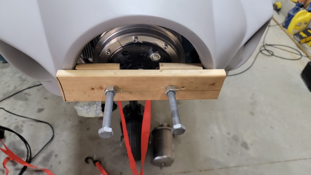
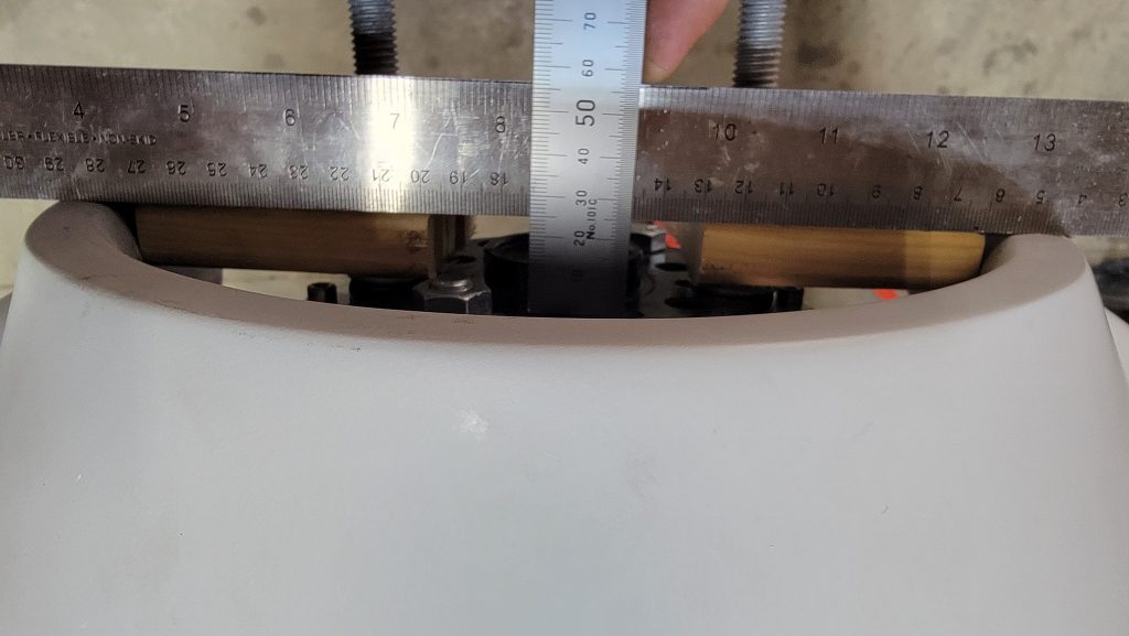
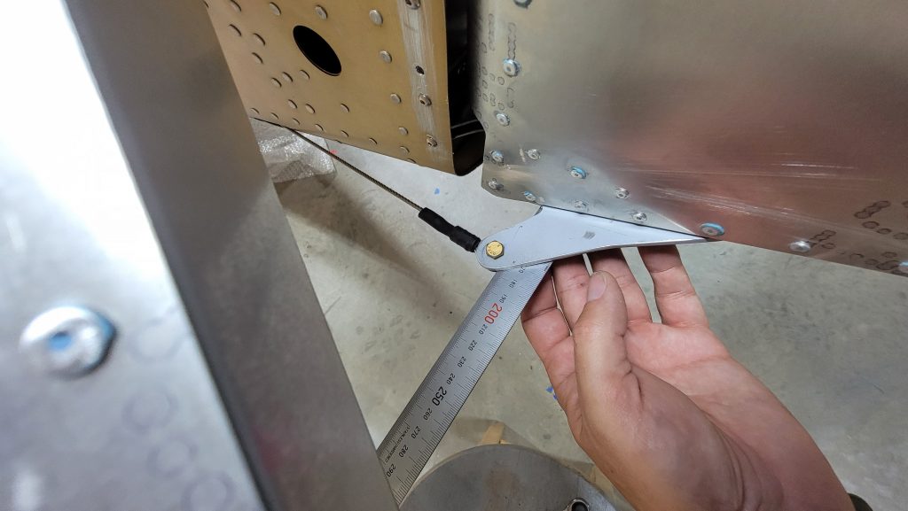
Okay so embarrassingly this took all day long. I built this little jig and added just enough washers to come out precisely to my calculated 25 mm clearance that I will need for my propeller,,, more information on my propeller to come,,,. That is 25mm between the front of the flange to the back of the spinner. Calculated at 31mm , minus 6mm.
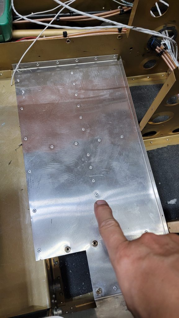
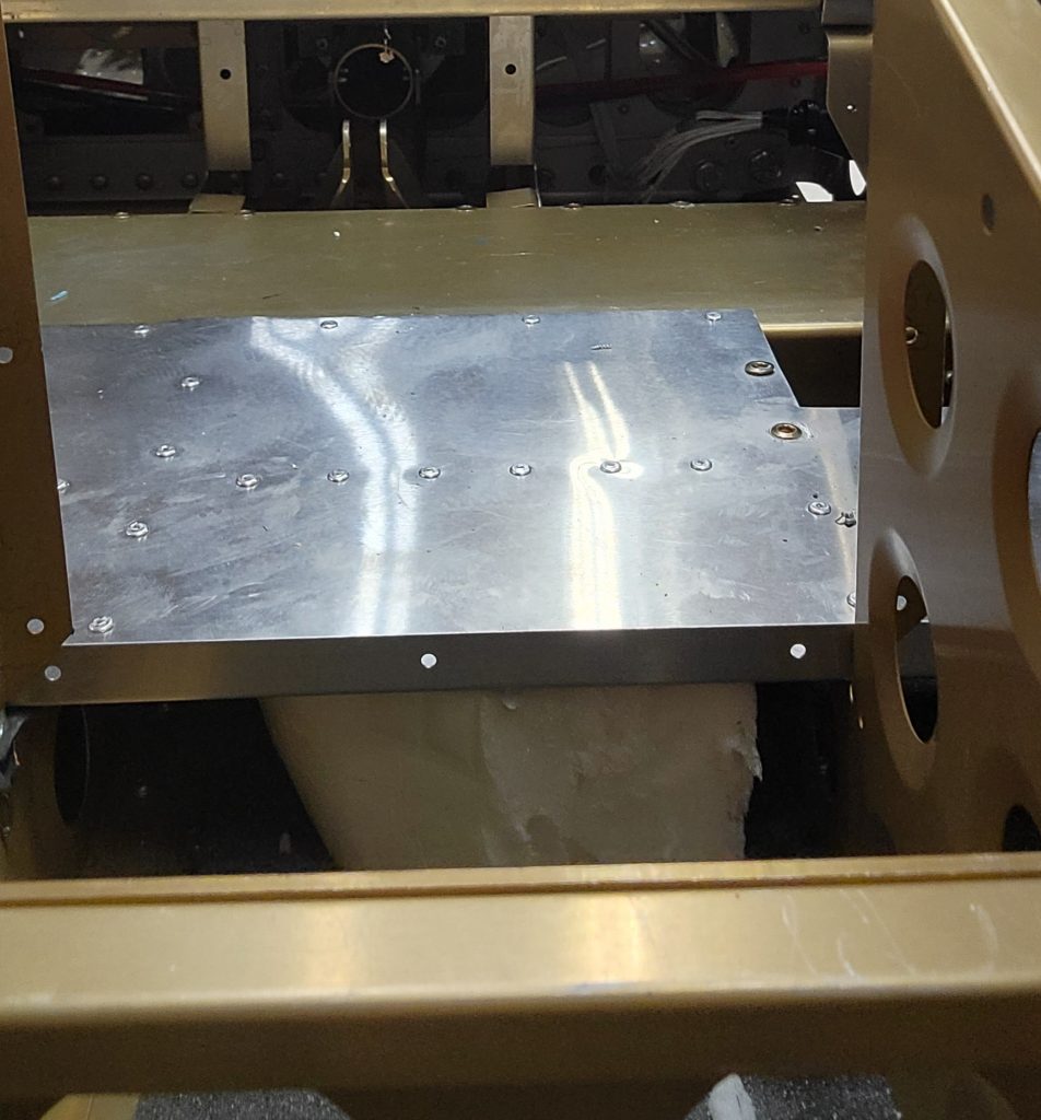
So I was concerned that where the passengers put their feet on the rear floor wasn’t solid enough. As you can see in the picture, the row of rivets I am pointing at is supposed to have a small brace under that thin piece of aluminum that they call the floor. The brace is only about half an inch deep. I didn’t feel like it would support enough weight. Or more accurately jumping and yelling and screaming kids. So I made the brace run all the way down to the bottom. So the new thicker brace that goes between the floor and the outer skin/bottom of the plane is 65mm tall. And then at the back bottom of that skin I put a piece of foam to fill the gap.
For better or worse it is definitely stronger now.
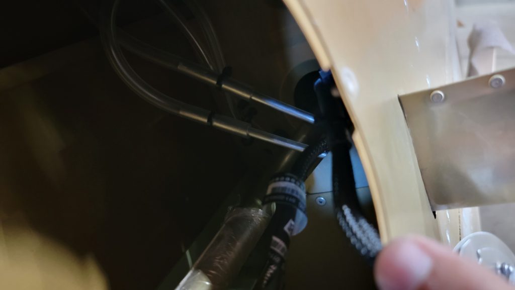
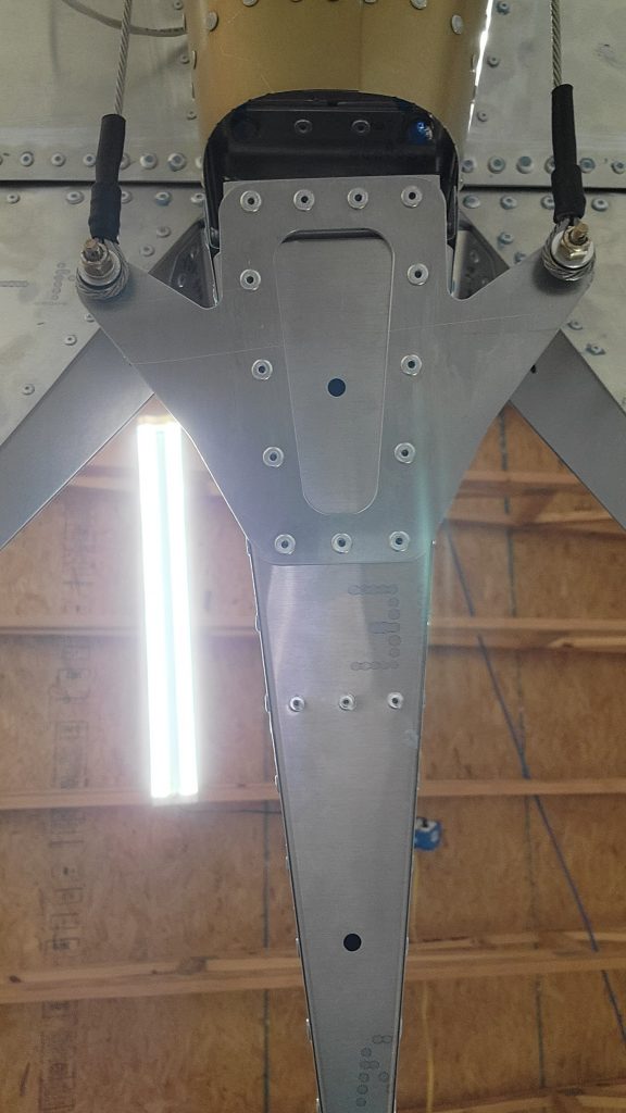
I chose to connect my pitot heat controller to the inspection hatch, has many others have done. I considered for a long time other places inside to mount it but none of them seemed as good as the hatch itself.
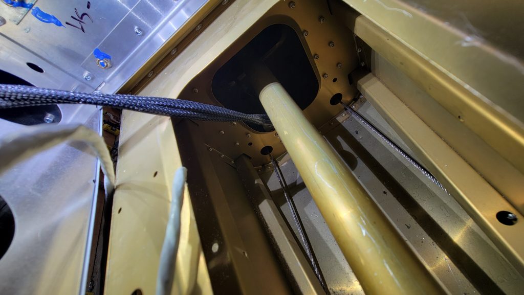
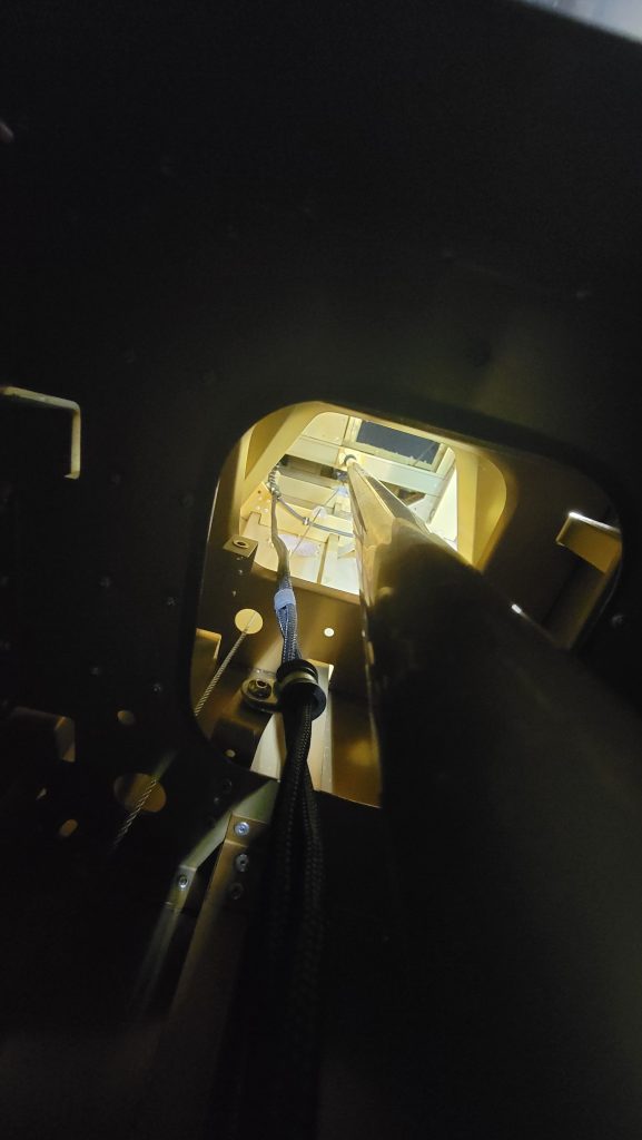
I was concerned that the pitot itself would go straight in and bang the aileron pushrod. If it goes straight in it will rub against the push rod. A slight bend of the aluminum pitot pipes towards the rear is all that was required to avoid the aileron push rod.
You can also see in one of the pictures the special tool I created to help tighten and loosen the inspection hatches.
I’m quickly running out of things to do. Because there’s only so many more things I can do without having my propeller or parachute. I have a couple things I’m trying to figure out this week that will hopefully help solve that problem.
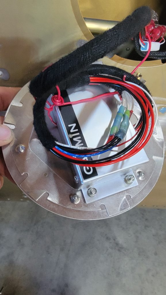
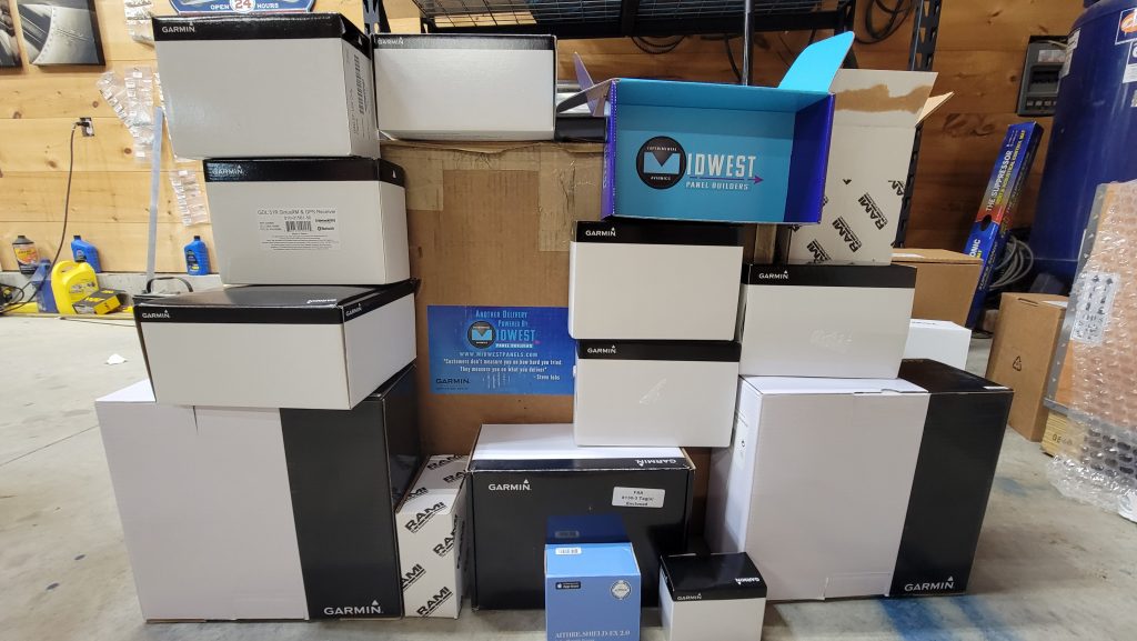
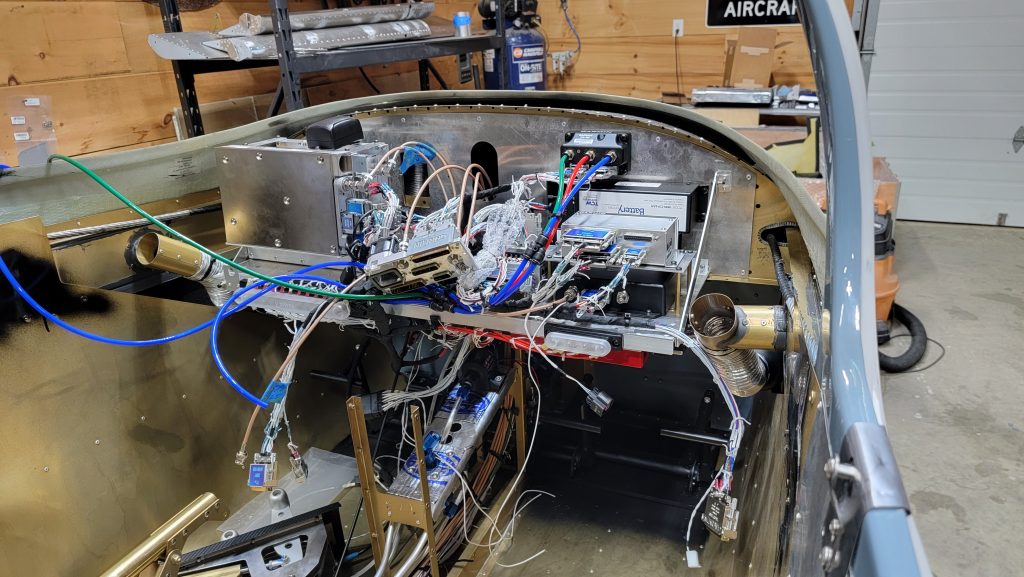
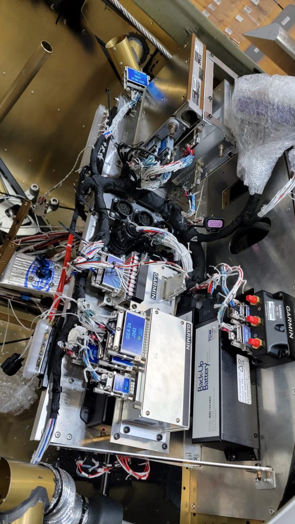
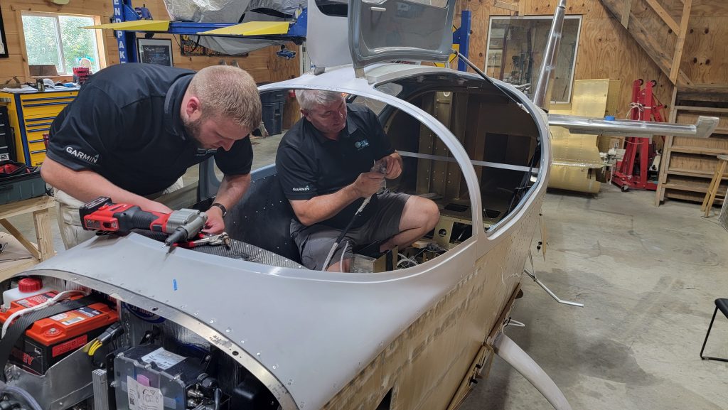
Christmas came early. I went back and forth a lot about whether I should do the panel myself or have somebody else do it. Deciding factor was that I want the highest quality install I can get and no one else has more expertise at installing avoincs, in Slings specifically, than Midwest Panel Builders. I definitely have the skill set to muddle through it and I could have figured it out but it wouldn’t be to the same level of quality that they can do it. So this week they have been here all week doing the panel installation. Now that they have been here and are mostly done, I’m very glad I had them do it. The amount of OCD and particularity that they put into their wiring is just unparalleled.
A huge advantage to having them do it that hadnt previously considered is, because they were here for a week,,,being able to ask them endless questions and be annoying as humanly possible to them has been a great education that I would not have gotten otherwise. A lot of us kit builders more or less buildings silently in our garage by ourselves. Being able to talk to somebody else and have them look at what you’re actually doing for any length of time,,, the value of that cannot be overstated. Not to mention it was just a lot of fun.
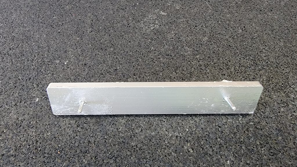
I did make some doubling plates for the antennas and I wanted an alternate static air source so I made a mounting bracket for that. So that gave me something to do while they were doing the wiring.
I’m not completely happy with the location of the antennas. I would much rather prefer them to be on the center line of the plane. But with the parachute and main support going down the center that just is impossible. They ended up being to the side of the parachute.
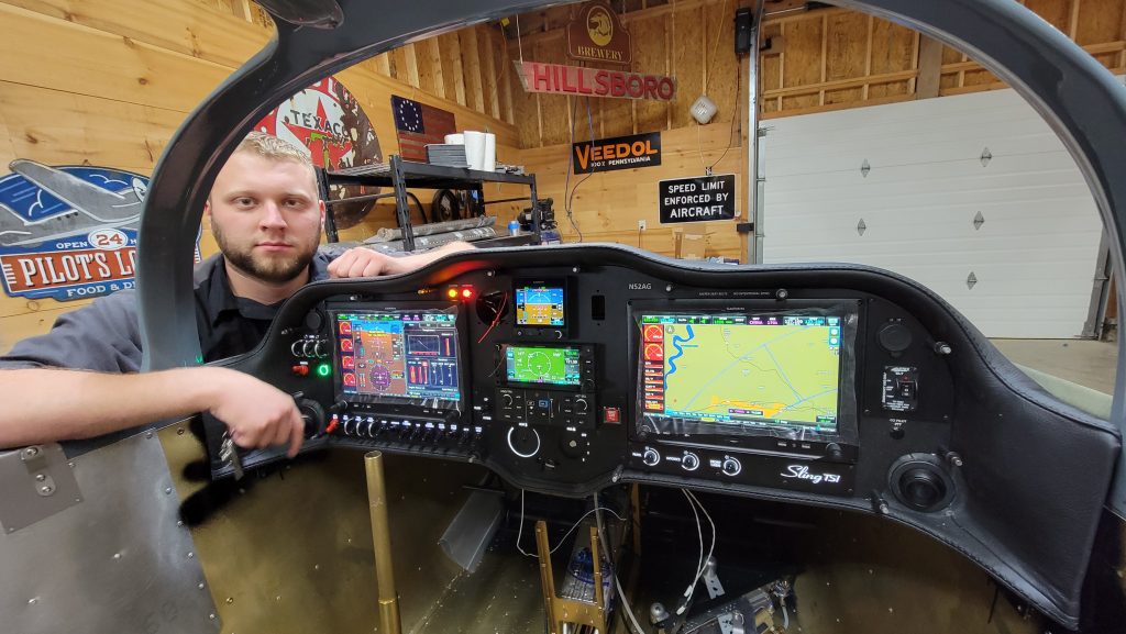
As mentioned in a previous post, I am getting the dual g3x and gtn 650 with smart glide and g5 and co2 detector options.
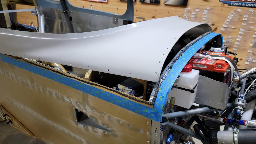
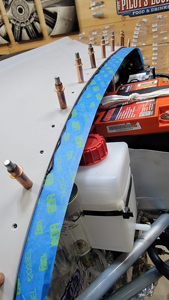
Front skin on. This went pretty smoothly. I was nervous about permanently sealing it up but did it anyway. I used RTV under the skin to make it water tight. I outlined the whole area with painters tape to help with clean up from over squeezed rtv. Remember to attach the defrost ductwork before you rivet it down.
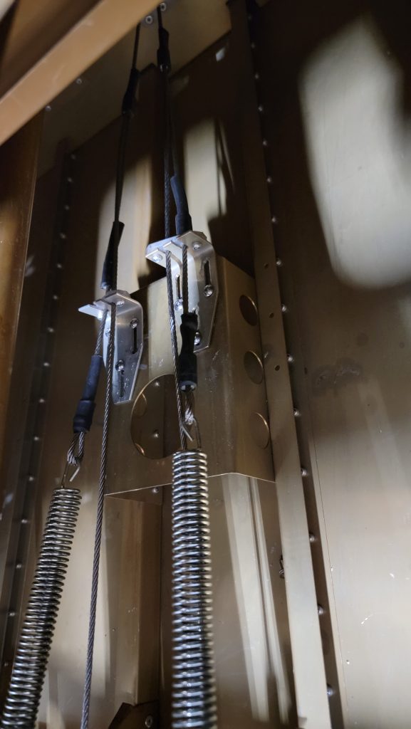
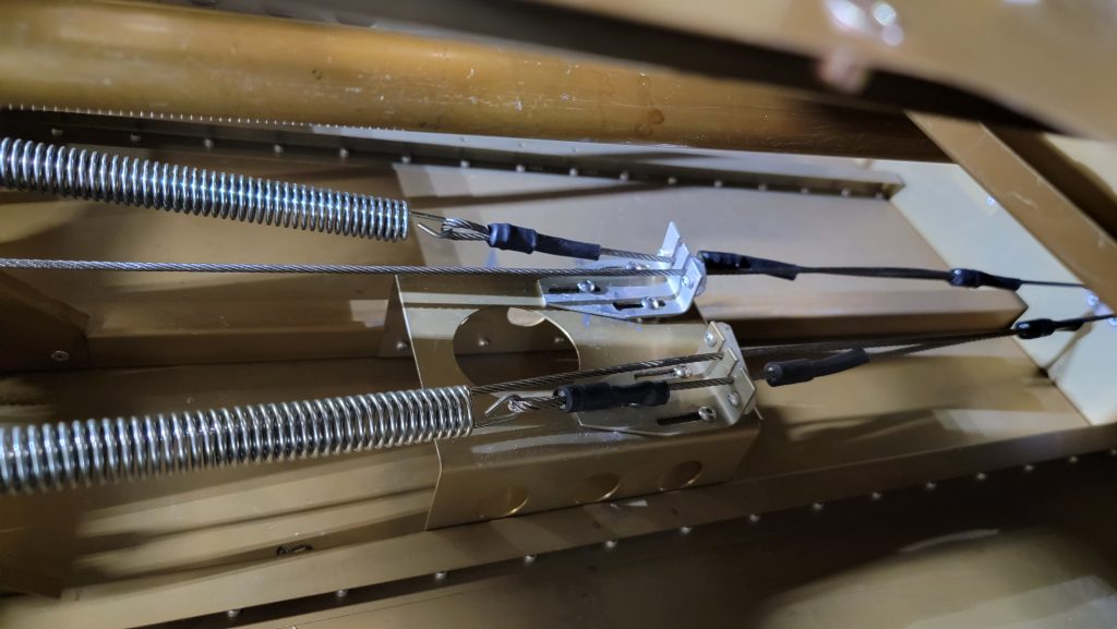
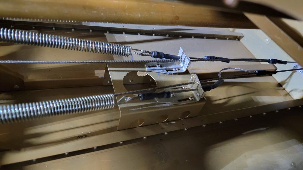
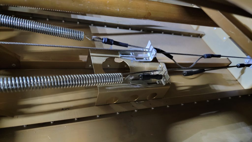
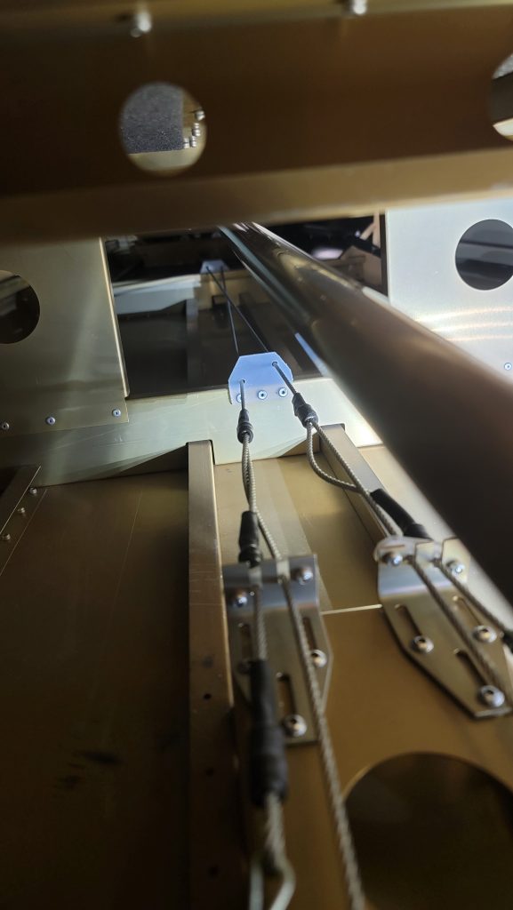
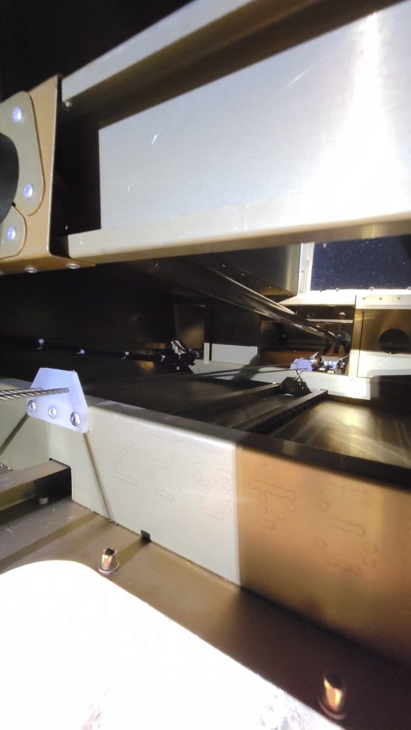
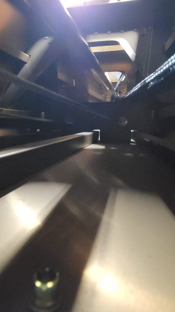
Trying to figure out what was causing my rudder cable to rub was a lot of work. About 3 days wasted. (I can count these hours towards the plane build right? Even if I am redoing things, or just staring at the plane itching my head? ) I’ll admit I couldn’t figure it out. So I took to the Sling Builders Facebook group to get ideas. A lot of people really stepped up to help out and give great ideas, thanks to Oliver and Midwest Sky sports. But it was an unexpected phone call from Jean that sent me down the right path. He suggested checking the sliding plates under the luggage floor where the springs connect. The suggestion was to disconnect the springs and then loosen the sliders. And then position the sliders where the stops on the cable naturally fall. So what this accomplished was that the cable going to the rudder on the opposite side that is being pulled, has very little pressure on it. So it may in fact be rubbing or touching but it has very little pressure therefore it won’t cut through/wear. He did also mention that if my rudder is correctly configured it should more or less auto center. At that point in time I couldn’t even imagine that ever happening because I was nowhere near that. I used the luggage weighing device and I measured how much force it was taking to turn my front wheel even while in the air…. Using the hole for the tow attachment,, it was taking 35 lb of force to turn my front wheel…. That is ridiculous…
So for the fifth time I dropped my front wheel and sanded down the bearings… That helped a lot… But still not enough… So I also remove the pedals and sanded down those bearings… I used to micrometer to make sure I didn’t take too much off. I sanded them down from 5.6 to 5.45mm. Then I haf to reattach the pedals and reattach the front wheel l. Now as if by some sort of magic my rudder auto centers, barely. Which to this novice is perfect. Now the front wheel while in the air takes 5lbs of pressure to turn.
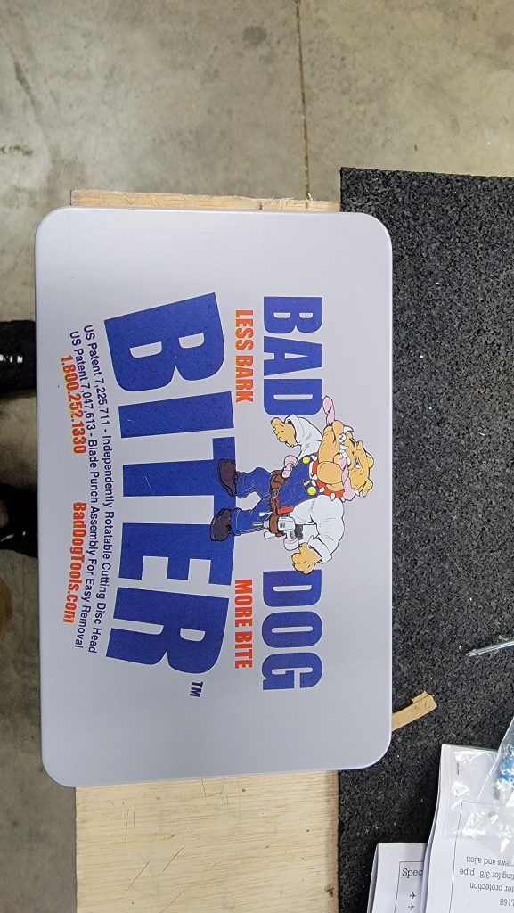
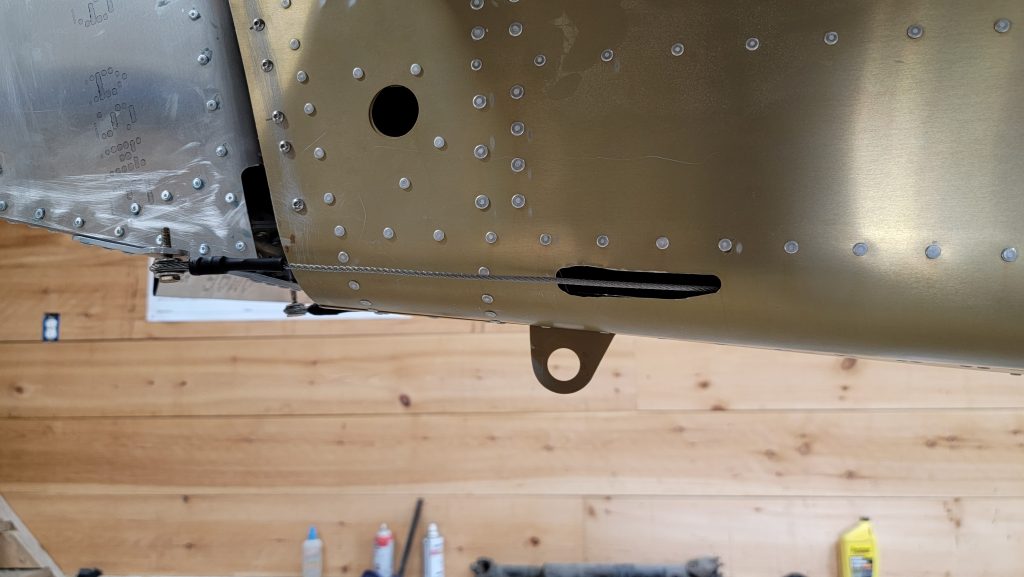
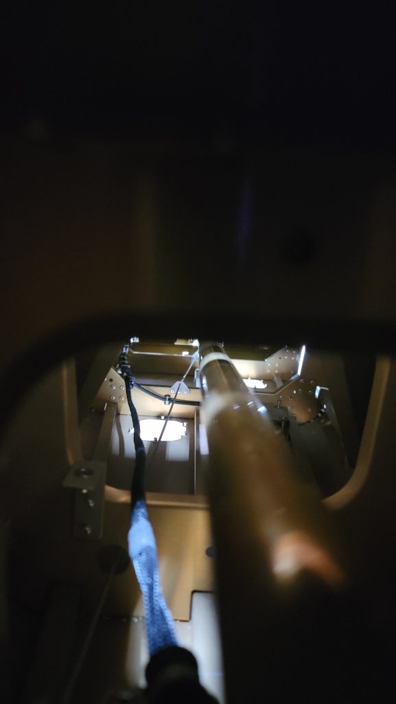
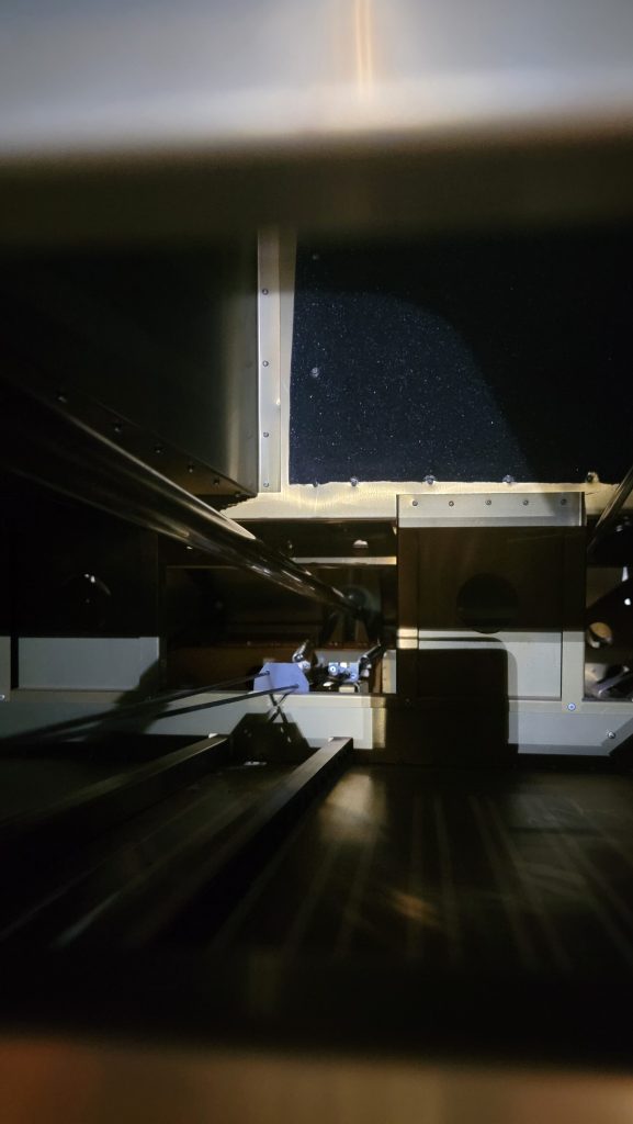
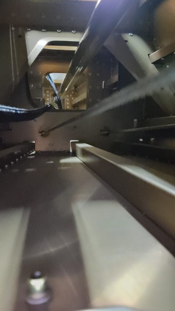
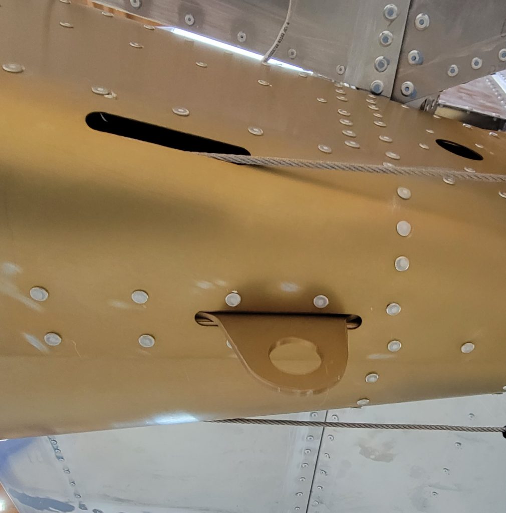
The cable going to the rudder, where it comes out of the rear fuselage, in my opinion was still rubbing too much. So I made the whole a little wider and a little further back. Jean also said this would be fine. I’m going to make a special piece of plastic to go over this hole which will make it look exactly like a normal hole. It’ll be just like the plastic (polypropylene sheet 3mm thick Amazon) that comes from the factory except a little bit wider. Should be a fun project for my Rotozip. To make the hole in the fuselage a little bit bigger, I was extremely nervous. But luckily this tool called a biter just made it like cutting butter, I could do it accurately and easily it was incredible.
Jean thank you for calling me after hours, your time, and spending 30 minutes listening to me uneducatedly babble about my problem. Your suggestions were invaluable. Thank you, Thank you.
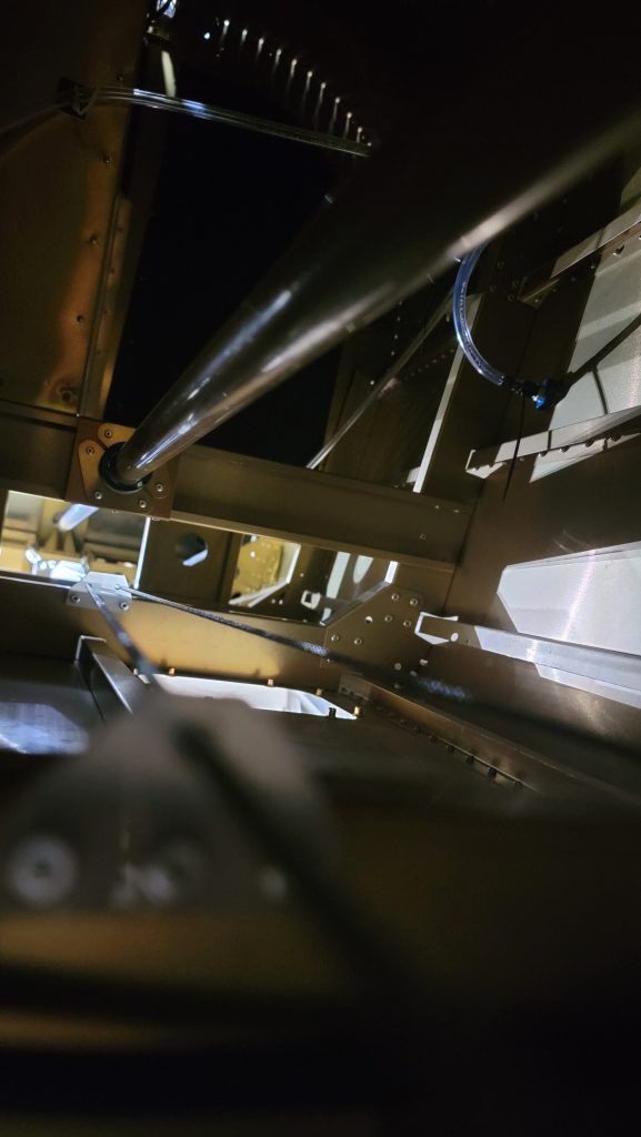
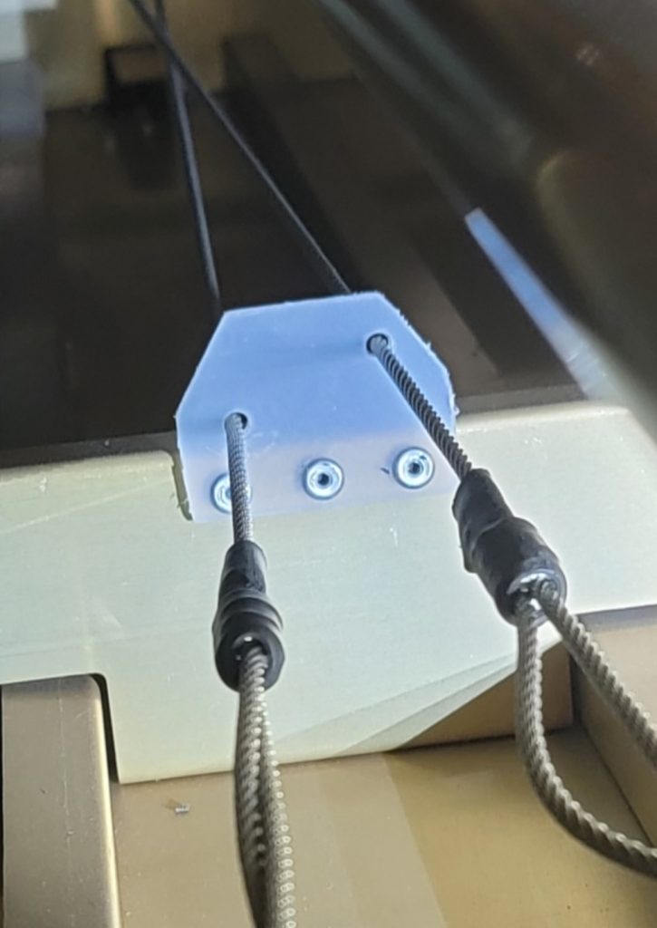
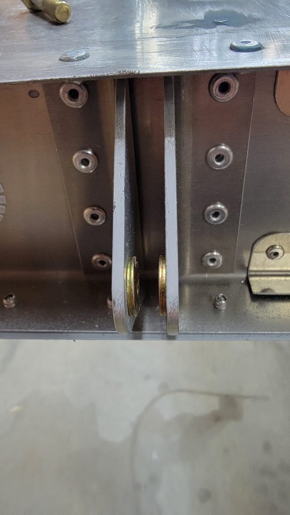
okay, for documentation sake, and helping to spread understanding, here is a picture of the rudder slide control ,,
Why is this happening? I can’t have my rudder cable bending around this corner. It’s about a 20 degree bend right against the fuselage. It will rub right through. Yes I know the plastic guard isn’t on yet. I am just test fitting. And yes both cables are attached. And both are attached to the pedals and the pedals attached to the front wheel.
I feel like I’ve said this too many times already,, but this simple task turned out to be harder than I thought it would be.
Getting all of the hinges on the elevator to line up the same time and all of the washers in the correct locations, was quite the challenge. So I took my lessons learned from that elevator and applied them to the rudder. I glued the washers for the rudder in place also. Don’t worry, as soon as the hinges were bolted down the washers spun loose immediately. For the elevator I found it easier to start at the middle and work my way out. For the rudderI found it easier to do the top bolt first then the bottom bolt then the middle bolt. The middle bolt caused me a lot of frustration but eventually it gave up and went in.
i thought this would be an easy productive day. You’d think I would have learned by now… Nope
i started trying to attached the elevator. The day before I attached the horizontal stab, that was actually easy. When I picked up the elevator I realized that one side of it didn’t have the rivets filled. So I filled the rivets in the morning and lucky they dried quickly. I sanded them and went back to installing. I quickly realized that I would not believe able to install the washers for each oly as required. So instead of trying to wedge the washers in there with needle nose pliers, I glued them into the HS ahead of time. Don’t worry it’s crappy glue, it barely holds. As shown in the picture I put a bolt through and temporarily wedged a bolt/spacefiller in there to hold the washers tight as they dried. They held just long enough for me to slide the elevator in. Then I attached two bolts. But,, then I realized that I should adjust the length of the pushrod first. The secret to that is pushing the elevator all the way forward at some times and all the way back at other times so that you can get the bolt and wrenches in there… So I did that…skip ahead 2 hours… Then I started to reinstall the elevator. Had to reglue some washers because they broke loose. Then I started to reinstall the elevator again. All the bolts aligned miraculously very straight and went in easy. Even the elevator tips aligned with the HS. Definitely use a laser level to make sure that HS and elevator are straight. I think that is what helped. Anyway,,, another day into the past.
Another day has gone into the past. I blew today by doing three tasks.
First, I flushed my fuel lines with FUEL. I know, I know , what a crazy concept. I previously tested them, to make sure there were no leaks, with water. But now that I was ready to complete the fuel lines, I didn’t want to connect the fuel lines to the engine with water still in the fuel lines. So I grabbed a high pressure self priming pump and pumped fuel through all of my fuel lines including the return lines. It was good because I got to test again that there are no leaks.
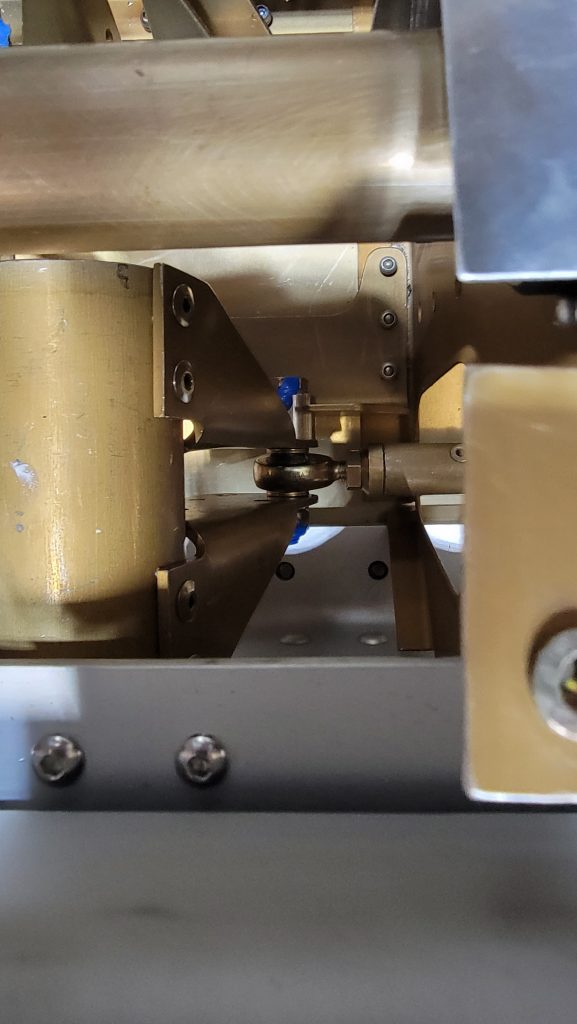
Second, I attached the aileron interconnect for the controls. This proved to be very challenging it’s very hard to get your fingers in there to put the bolt, washers and nut in place. I ended up putting the bolt through the opposite direction from what the instructions say but I think it’ll work fine. Functionally, there’s no difference. The bushing is still on the side required to act as a stop. Putting that stupid pushrod in took a very long time.
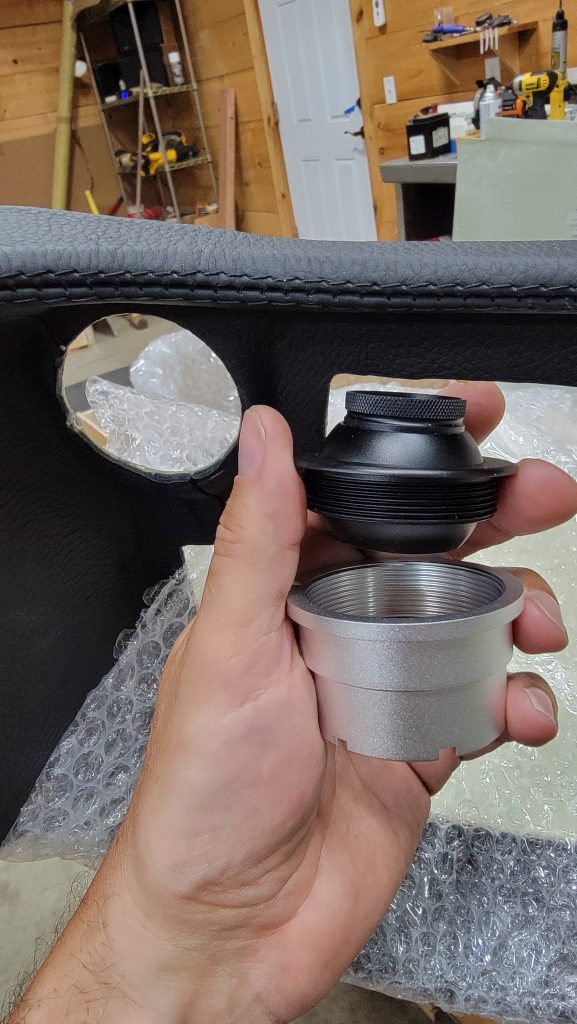
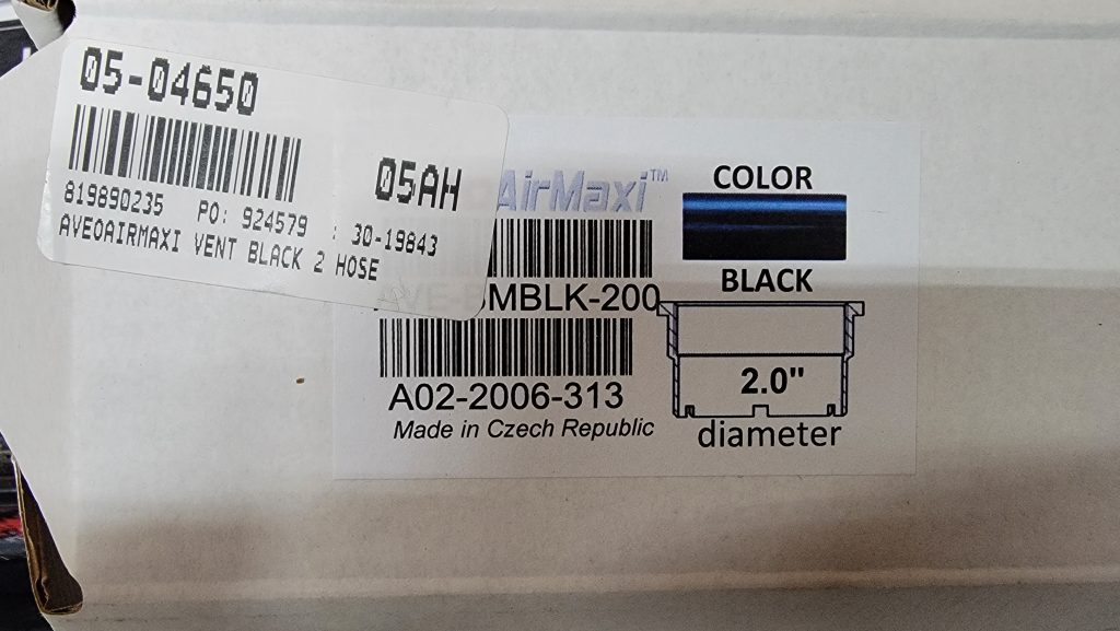
Thirdly, I replaced the air vents that come with the dash with the Aveo vents. Literally the easiest thing I have done to build this plane. It took me less than 5 minutes to do both of them.